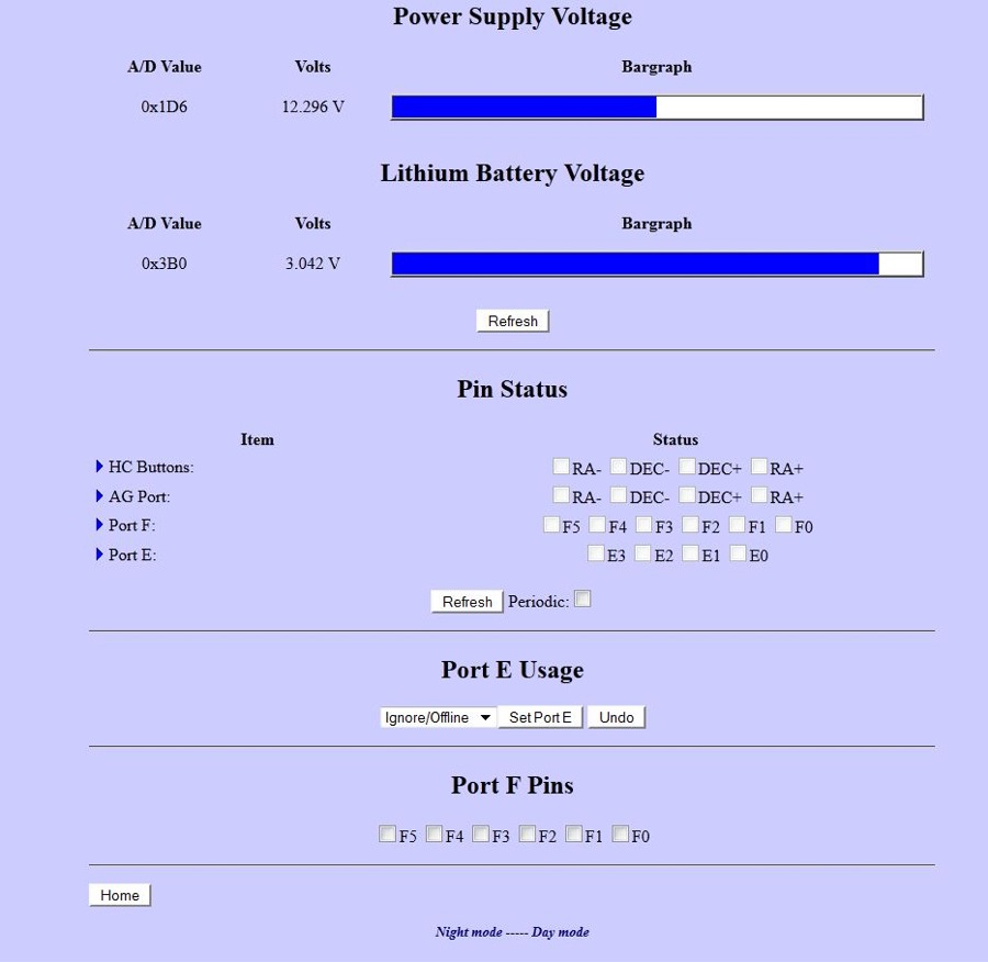
- Power Supply Voltage - This bar graph shows the external power being supplied to the Gemini-2. It will turn Yellow, and then Red if the power supply voltage is not high enough. Note that the Internal Processor has code that will try and save the current setting, but stop motor movement if the power supply drops too low.
Remember this is just a demo page, use the link at the bottom to see
the real value.
- Lithium Battery Voltage - This is the bar graph of the internal
Lithium battery. This battery is used to back up the internal
SRam and Clock circuits. Without it, the Gemini-2 would not
remember much of the current setting, and they would have to be
reprogrammed upon power up. The internal battery is a CR2354.
Remember this is just a demo page, use the link at the bottom to see
the real value.
- PIN Status - This is the pin status of all the external ports on
the Gemini-2
- HC buttons - These are the buttons on the
Classic hand controller, that can be
plugged into the Classic hand controller jack. This hand
controller can be purchased from Losmandy. It is on there
replacement parts web page. I really recommend it.
It can also be used to test the Guider inputs.
- Use the Periodic check box to have these inputs show up as
they are activated. Otherwise you will have to use the Refresh
button to try and catch them.
- Port E Usage - This port has several usages:
- Ignore/off - pretty much means what it says. This port
is not monitored.
- Axis Encoders - This would use external encoders if plugged
into this port and this selection selected. The only problem
with this is that the Firmware in the Gemini-2 does not at this
time use the external encoder values, as the ones sold by
Losmandy has a much lower resolution than the ones on the back
of the motors. This cause the Gemini-2 to loose accuracy
if the external encoders are use.
- End Switches - If this is selected, then any one of
the pins 1, 3, 5, 7 if taken to ground (shorted to pin 8) will
stop all motor movement in both RA and DEC. Note that
these pins are +3.3V inputs Max, and supplying more than that
could damage the internal ARM processor. These pins need
to be pulled up to +3.3v through 1K resistors for each
input.
- The +5V pins on this jack was intended to supply power to
external encoders. Do not use this voltage to provide
pull-up voltage for the inputs of this jack.
- Port F Pins - These check boxes are used to activate the
associated pin, so that it can be used. If the checkbox is not
checked, that input pin is not used.
|