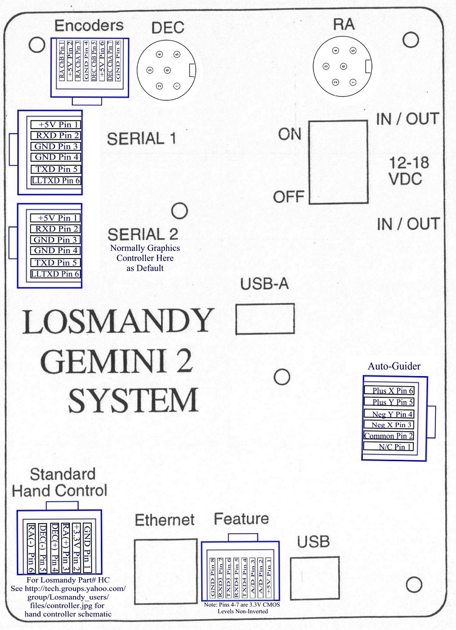
Jack (Jack Socket) descriptions: Going clockwise from top Left.
- Port E -
THIS IS
NOT AN ETHERNET CONNECTION. DO NOT PLUG A ETHERNET CABLE INTO THIS JACK. This jack can
only be set up to detect external limit switches,
and stop the mount if any one is detected. It functions
just the same as the Gemini-1 Encoder input jack for this
purpose, so the
Level 4 Gemini-1 manual description is accurate for this
jack.
See page 127 and 128. The Level 4 manual refers to them as
End Switches. You can turn them on and off using either
serial command 312, or the web interface page Batteries/Ports (Example
Battery/Ports page).
Serial
commands 14 and 15 used to enable or disable these inputs
respectively.
- DEC connector -
this is to the DEC motor. This is the top motor on the mount.
The wiring is the same as the Gemini-1 with Din connectors. See
page 130 of the Level 4 manual for a description of the
pin-outs. PLEASE DO NOT CONNECT or DISCONNECT the MOTOR
CONNECTORS with the top panel removed. The top panel provides
the necessary support to keep these connectors from cracking a
connector pin from cable strain.
- RA - this is to the RA motor on the telescope. This will be the bottom motor.
The wiring is the same as the Gemini-1 with Din connectors.
See picture of
Losmandy made motor cable for a description of the pin-outs. PLEASE DO
NOT CONNECT or DISCONNECT the MOTOR CONNECTORS with the top
panel removed. The top panel provides the necessary support
to keep these connectors from cracking a connector pin or PCB
connection.
- Top Power jack and Bottom Power jack -
(There is only one power jack on the new version of the
Gemini-2) these jacks are in
parallel and either can be used as input. The only thing is that
each has a 5 Amp fuse in-line before they are tied together
inside the Gemini-2. The second is used to
help provide power to accessories. The center pin is
positive. They are 2.1mm/5.5mm size connectors. I recommend 5
amp rated connectors, I recommend the Switchcraft 762 or 763
series. The
CA-2191
Right Angle Connector with 6Ft leads from Digikey work
nicely also. They have an 18Gauge wire. Mouser also
carries a similar cable from
Kobiconn Part Number 172-4207. They only have 24"
leads. The panel inputs are in
parallel, but do have a 5 Amp Fuse and protection diode so that the wrong
polarity will not damage anything inside the Gemini 2, but it
could damage any accessory you have connected, to the other
jacks. I recommend a CINCON Medical Power supply 90-267V AC
input with 15V 6.67A output part number
TR100M150-11E12-LVL-V from Mouser Electronic, This
power supply has powered my Gemini 1 and is now powering my
Gemini 2. It's plug will fit directly into the Gemini 2
power plug. The 15 Volts is directly in the middle of the
recommend 12-18V DC range recommended by Losmandy. Please note
that if you use anything besides 12 Volts as power, the second
jack is going to put out the same voltage as the supply voltage,
I.E. 15V in will be 15V out on the other power connector.
- Autoguider input. - This is a standard ST4 compatible auto-guider input
jack. It is used to provide guide signals into the
Gemini-2 while tracking. For it to function the Gemini 2
has to be either in the Photo mode or the All-Speed mode.
In the hand controller see Menu-->HC-->Mode. The standard
hand controller described under the hand controller port
can be plugged into this port to test the ST4 functions.
If using the older version of the standard hand controller, the
led will not light up, but the buttons will function to simulate
ST4 inputs.
- USB port - this is the USB port that you will use (the USB-A
port in the center of the panel is not supported.). There are
only drivers for Windows and Linux at this time. Linux
supports it directly. See the driver section for the
Windows drivers.
- Info about using the Gemini-2's USB port: The Gemini-2 USB
device connection works. Its use is widely supported, by ASCOM,
GCC, Stellarium, ... since it just shows up as a virtual COM
port. Just plug your setup together and try. If it works it
works.
- Some quirks and limitations are caused by the USB standard (most
important the limitation of the cable length). Some operating
systems like Windows add additional inconveniences by
enumerating the VCOM ports differently if different USB sockets
are used.
- Regarding these different sockets a PC provides... most PCs
already have USB hubs inside for offering multiple sockets. So
the real question would be if there's someone using the USB
connection w/o a hub. Another question would be, how far the
USB connection can be extended using cascaded hub and I'm sure
that Gemini-2 will work very gracefully even at the limits of the USB
specification. Normally by USB standards only 4 hubs
maximum are allowed, which provided a limit of 64 feet.
- Gemini-2 offers the USB device communication as convenience in
parallel to supporting the serial ports (that modern laptops
don't offer anymore) to get rid of the annoyances of
Serial-to-USB adapters.
- Most of the people that have tried the Ethernet connection just don't want to miss it,
because it makes a world of a difference. You get web access, remote connectivity,
wireless if you want. Gemini-2's UDP datagrams offer a consistent view at all
important variables (coordinates, time, ...) at
one glance within a millisecond, something where serial protocol
from RS232 over USB up to TCP can't compete. It is simply perfect.
-
There can be some advantage in using different technologies like USB and Ethernet in parallel - but not for Gemini-2,
but for camera devices that want to transmit huge amounts of data over USB.
So there's no real need to tunnel all data through one technologies ...
but surely it can be done, if there are reasons to do this.
-
The USB function in the Gemini-2 does not provide for a USB
Hub.
- USB-A This USB-A is not supported at this time. About the only
thing it can be used for is to provide +5V at 500MA or less.
- Feature Port or Port F- This is an expansion port. The signals
on this port
has many different uses. It provides 2 extra 3.3V TTL
serial ports. (you will need level converters/inverter to use these) and
a couple of Analog to Digital inputs, plus +5V and ground
signals. The only accessory for this port at this time is
a
USB Adapter Cable, that can be used with MAC and other
computers that you will have to make yourself.
- Ethernet Port - this is a standard 10/100 speed
Ethernet
connection. See connecting to Ethernet port under the Gemini-2
menu at the top of this page. The Gemini-2 does support
DHCP, so that a router can assign it a IP address. Without
DHCP, the default IP address is 192.168.0.111. All
Gemini-2 units ship with the same MAC address. Both the
default MAC address and default IP address are changeable in the
Web interface in the network tab. If your network supports
NETBIOS, the NETBIOS name for the Gemini-2 is gemini, so instead
of http://192.168.0.111, you
could use http://gemini to get to
the web interface. (Both links will only work if the
Gemini-2 or Gemini-2 Mini is connected via Ethernet and and your
system supports netbios in the latter case.) Please note: If your computer
does not have a Ethernet connection that supports auto-detection of cable type,
and is is only a 10/100Mhz speed connection, then you are going to have to
use a ethernet crossover cable. I suggest you Google Ethernet crossover cable to
get more info.
- Standard Hand controller -
(This connector is missing on the new version of the Gemini-2) this is the same hand controller
that is supplied with Losmandy's stepper motor mount controller
system, and was the first hand controller used with the Gemini-1. It can be ordered separately from Losmandy. Part
number HC. Note: this hand controller does not function
like the buttons on the Graphical hand controller front LCD. It
functions like the hand controller on the Gemini-1, or the
buttons on the back of the Gemini-2 hand controller. If you
need to speed up, you have to press the opposite button to the
one you pressed first (it must be held down also when pressing
the opposite button to change speed.) Each press of the
opposite button while holding down the desired directional
button should take you to the next
speed range. Guide-->Center-->Move-->Slew.
You can see a picture of both versions
here. Losmandy has just introduced a newer
version using a membrane panel like on the back of the Gemini-2.
you can see a picture
here, and
here is the order page. This is the
schematic that is posted on the
Losmandy users group of the older model. This schematic is
on the Losmandy users group under files and is named
controller.jpg with a description of Hand controller.
- Serial Port 2 -
THIS PORT IS NOT COMPATIBLE WITH THE GEMINI-1 SERIAL CABLE. (This port has been relabeled on the new version of the Gemini-2
to "HC". This is the
default serial port that the Graphics hand controller
connects too. The baud rate
has to be set to 57600 baud to communicate with the Graphics Hand
controller. A firmware update or Sram reset will set this
serial port the to default setting of 57600. Note: The graphics
hand controller will only operate at 57600 baud. On the
Gemini-2 it uses +/- 3.3 Volts for the working voltage, although
the inputs to the serial connections can swing from +25V to -25V with no damage,
On the Gemini-1 units the output voltages in +/- 5 Volts with
the same +\- 25 Voltage swing inputs on the serial pins and still be safe.
- There are two versions of the hand controller. The
first version can be noted by the 5 small switches that is
under the gasket at the bottom of the screen. You can
barely see the white tops of these switches, if you can see
them at all. The top PCB board in this version is blue
in color. The micro-SDcard is on the bottom of the top
PCB board. The top PCB with the LCD on it was a
commercial product sold by another company. It is no
longer being manufactured.
- The Second Version is totally produced by Losmandy,
except for the LCD itself. Hopefully this version will be
in production for many years. The micro-SDcard is on the
bottom board of the two board set. It came into prototype
in 2012, and delivery in late 2012 or early 2013,
the best I can find out. Both this version and the
first version have the same size LCD. This version
does not have the 5 small switches at the bottom of the LCD.
- Serial Port 1 -
THIS PORT IS NOT COMPATIBLE WITH THE GEMINI-1 SERIAL CABLE.
(This jack is relabeled on the new version to Serial/GPS) This is the serial port that you normally
use to connect to either a computer, or a GPS unit. The Gemini-2
will poll upon power up to see if a GPS is connected, and then
set the time, date and locations from it if found. For serial
port cable wiring see
cable_wiring.php.
To set the baud rates, you have to go into the web interface
(See connecting to
Ethernet port ) and then select the menu option Serial Ports
(Serial Port
page. <-- Link only works if Gemini-2 is connected to
computer displaying this web page, and responds to http://gemini) By default the Gemini-2 sets this port to 9600 baud
if a firmware update is done, or Sram is reset. At power
up it will take the serial port to 4800 baud to look for a GPS,
and then set it back to the baud rate selected in the Serial
Port page. For more on GPS receivers and using them
please see GPS receivers
|